Load groups and normal or standby operation
Normal, standby-supported and UPS-backed loads may follow different supply paths. The transformer duty must reflect the project's actual operating arrangements, including any approved alternative supply state, rather than a generic airport redundancy label.
Information to provide: Single-line diagram showing source and load groups, operating-state descriptions, expected duty in each state, future allowances and the party defining essential-load requirements. Identify generator, UPS and transfer-switch interfaces where they affect the transformer brief.
Motors, drives and electronic equipment
Building services, baggage equipment and other connected loads can have different starting and operating characteristics. A total running-load figure alone does not describe every condition relevant to a transformer proposal.
Information to provide: Load schedule for HVAC, pumps, lifts, conveyors and other relevant equipment; starting methods and simultaneous duty; UPS or drive input data; available harmonic information; and the designer's specified electrical performance and loss-evaluation conditions.
Room conditions, exposure and occupied areas
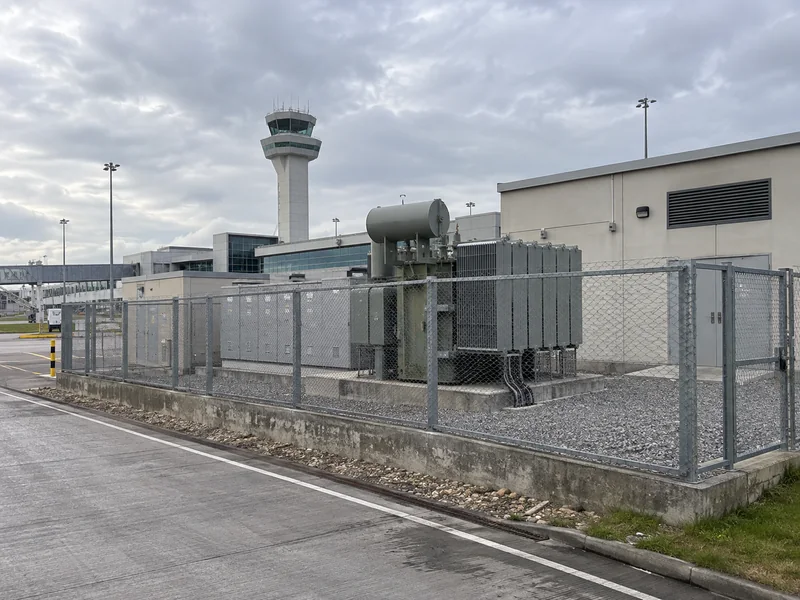
Transformer type, enclosure and installation layout need to be considered together. Heat rejection, access and the site's fire strategy are important in electrical rooms; noise criteria may also matter near occupied spaces. An indoor location alone does not settle the configuration.
Information to provide: Room or outdoor layout, ventilation concept, ambient temperature and altitude, moisture or corrosive exposure, access clearances, relevant fire or containment requirements and any noise limit with its measurement conditions. State which requirements come from the airport or local project authority.
Electrical terminals and monitoring interfaces
The proposed connections and accessory signals must match the surrounding installation. Monitoring integration is not established simply by describing a transformer as smart or by providing an unspecified communication option.
Information to provide: Cable or busbar entry, terminal drawings, earthing arrangement, fault data and required vector group or impedance if specified. Include alarm, trip and temperature signals, the receiving monitoring system and any agreed communication protocol, with the responsible integration party identified.