Skip to Content

TRANSFORMER APPLICATION

Transformers for Data Centers

Start with the transformer's position in your data center power system. The duty for an IT power block, cooling equipment or an expansion project can differ. Share the electrical design and installation requirements so the proposed transformer and quotation can be checked against the same scope.

Discuss Your Project
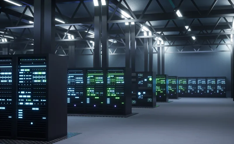
Rows of server cabinets in a data center hall

Start with your project task

Supply a new IT power block

Define the transformer's role before selecting a capacity or assuming a standard connection to the UPS system.

Send these inputs
Project country and specification, single-line diagram, required voltage ratio and frequency, proposed transformer rating, IT load forecast, UPS information and the intended utility/generator operating arrangements.
Review and coordination
Identify the transformer duty and the electrical interfaces to be addressed in the quotation. The project electrical designer confirms loading and system assumptions for normal, standby and bypass operation where applicable.
Expected output
A defined transformer supply requirement, a list of open technical questions and a basis for comparing the offered configuration.
Discuss This Task

Power cooling and auxiliary equipment

Cooling and building-service loads need their own duty assessment; the IT load figure does not describe every transformer in the facility.

Send these inputs
Chiller, pump, fan and other auxiliary load schedules; motor starting methods; drive data; operating cycles; and any separation between IT and mechanical distribution.
Review and coordination
Review the requested transformer rating against the mechanical-load duty and installation location. Have the system designer check starting, load steps and interactions with the selected source and distribution equipment.
Expected output
A mechanical-load transformer requirement that identifies the load assumptions and the information needed for an electrical quotation.
Discuss This Task

Add a phase or replace an existing unit

Keep the existing interfaces visible when increasing capacity or replacing equipment. Matching the kVA rating alone does not establish interchangeability.

Send these inputs
Existing nameplates and drawings, current single-line diagram, measured demand where available, added-load schedule, terminal photos, access dimensions and the proposed installation window.
Review and coordination
Compare the required rating and interfaces with the existing records. If parallel operation is proposed, the designer checks compatibility rather than assuming units can operate together. The site team confirms measurements and the replacement or expansion method.
Expected output
An interface and information checklist for the new unit, including any design questions that need resolution before a configuration-specific quotation.
Discuss This Task

Conditions that affect configuration

Electrical architecture and fault duty

Transformer rating and impedance affect downstream fault-duty and voltage calculations. Source and switching arrangements also affect the review; neither the IT load nor a redundancy label defines the complete transformer specification.

Information to provide: System and winding rated voltages, frequency, vector-group and earthing requirements, specified impedance, available fault-level/protection study and relevant utility, generator and UPS operating modes.

UPS, drives and nonlinear loading

Harmonic currents can add heating and losses. Their significance depends on the equipment and operating profile, so request a duty assessment rather than automatically assigning one K-factor grade to every data center.

Information to provide: UPS and drive manufacturer data, topology and loading profile; harmonic spectrum or study if available; and measurements for existing installations. Identify any separate harmonic-mitigation equipment.

Losses, room temperature and sound

Compare loss values under the same stated conditions and expected loading profile. Room ventilation, enclosure airflow and acoustic requirements need to be considered with the offered cooling arrangement, not after the room layout is fixed.

Information to provide: Ambient design conditions, room ventilation drawings, enclosure requirements, proposed load profile, specified loss and temperature-rise conditions, sound limits and measurement criteria.

Access, terminals and monitoring interfaces

The transformer and its enclosure have to fit the delivery route and installation arrangement. Cable or busduct connections, maintenance access and alarm interfaces should be identified before the final drawing is agreed.

Information to provide: Access route and lifting limits, foundation/room dimensions, cable or busduct entry positions, clearances, and required sensors, alarm/trip contacts, fan controls and monitoring interfaces.

Explore suitable product options

Dry-type transformers

Explore this range for building-integrated electrical rooms and suitable distribution duties. Confirm the required rating, enclosure, ventilation, sound limits and electrical interfaces. A dry-type selection does not remove the need for project-specific installation and fire-safety review.

Review product range

Oil-immersed transformers

Explore this range for outdoor intake areas or dedicated transformer installations where permitted by the project design. Confirm the voltage and load duty together with fire separation, containment, site access and maintenance requirements.

Review product range

Documents by project stage

RFQ and technical comparison

Identify the offered electrical configuration, loss and temperature conditions, accessory scope, exclusions and unresolved requirements. Include the project specification and required-document list so quotations can be compared on the same basis.

Stage: quotation

Configuration and interface approval

Agree the applicable general arrangement, dimensions and weight, terminal positions, nameplate information and accessory wiring for the selected configuration. The project team checks these against the installation design; a generic illustration is not a construction drawing.

Stage: design approval

Inspection, shipment and handover

Agree the inspection plan, acceptance criteria and required test records before ordering. Special or witnessed tests require an agreed scope. Confirm the applicable manuals, packing and shipping documents, plus the site responsibilities for receiving, installation and energization.

Stage: delivery

Scope and coordination

This page concerns transformer supply requirements, not the design or certification of the complete data center. The project designer coordinates the power architecture, earthing, protection and interfaces with the UPS, generators and switchgear. The owner and site team control installation, maintenance and operational acceptance. A transformer selection does not establish a facility Tier classification or guarantee uninterrupted service. System studies, site services and equipment outside the transformer scope are included only when expressly agreed in the quotation.

Questions before requesting a quotation

Does a K-rated transformer remove harmonics from the system?

No. A K rating addresses the transformer's ability to tolerate specified nonlinear-load heating; it is not a promise of harmonic cancellation. Assess the actual load and system first, and treat any required harmonic-mitigation solution as a separate design decision.

Can I choose the transformer using only IT load and an N+1 or 2N requirement?

No. Identify which loads the unit supplies and how the system operates when equipment is unavailable or bypassed. The electrical designer establishes the required duty and redundancy arrangement; the transformer quotation should respond to that requirement.

Is the existing nameplate enough for a replacement quotation?

It is a useful starting point, but also provide the existing drawing and connection arrangement. Access, enclosure, terminal positions and site measurements need to be checked before treating the replacement as mechanically and electrically interchangeable.

What should I send if the design is not finalized?

Send the project location, known supply voltage and frequency, intended transformer role, available load information and installation constraints. Include a specification or drawing link if available. State which values are preliminary so missing design decisions remain explicit.

Send your project requirements

Share the voltage, capacity, installation conditions and project specification. A document link is optional.

Request a Technical Discussion