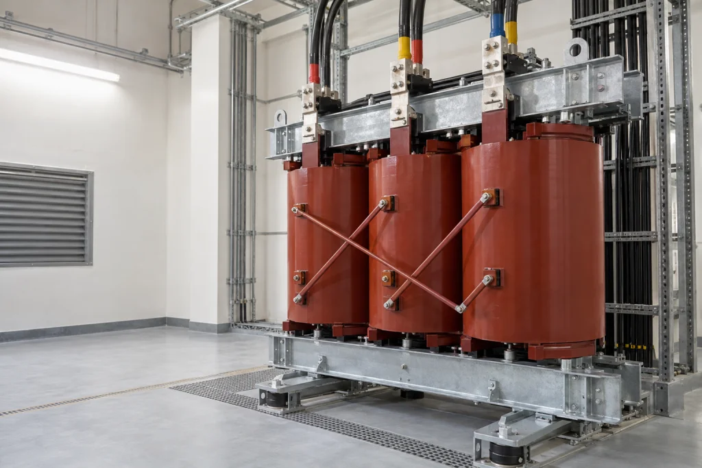
A cable-entry direction does not settle whether the conductors can reach and fit the transformer terminals while preserving connection space and airflow. As an EPC electrical engineer, you need a coordinated arrangement for the selected cast resin transformer. I recommend agreeing that arrangement before releasing the manufacturing details it affects.
Start with these inputs:
- The selected transformer model/configuration, outline drawing and electrical connection diagram.
- Cable type, size, connector details and parallel termination quantity, or the proposed busway connection.
- The proposed entry route, cable bending space, ventilation openings and external conductor supports.
The following review keeps instructions for cast resin, VPI and low-voltage equipment within their respective scopes. It prepares the connection interface for procurement; the selected suppliers and project designers still confirm the applicable details. 1234567
Which entry details belong on coordinated drawings?
Agree the selected transformer configuration, HV and LV connection arrangements, enclosure entry face and elevation, and terminal geometry on coordinated drawings. Treat gland-plate openings as a separate approval, then resolve supplier comments before releasing the affected manufacturing details. 1278
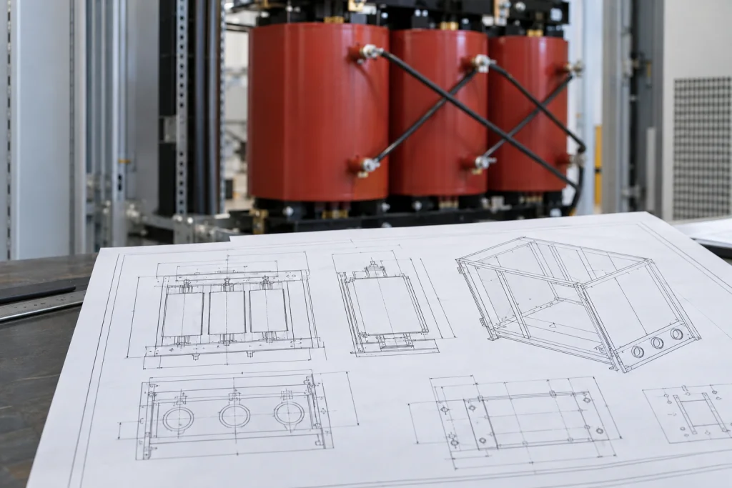
When I review an entry arrangement, I check the enclosure opening and the terminal position as separate interfaces. The ABB low-voltage installation guide ties cable entry to the outline drawing and required bending radius. Its side-entry recommendation preserves ventilation areas; it is not general permission for side entry on another model.
For your selected configuration, request drawings showing:
- Each winding's connection arrangement and the proposed enclosure entry face and elevation.
- Terminal positions, orientation, connection-hole pattern and dimensions needed to assess the proposed connectors.
- Gland-plate location and proposed openings, with the machining location, responsible party and supplier approval recorded.
Siemens' cast resin manual describes connection holes at the upper and lower ends of the HV connecting rod and calls for sufficient connection space and electrical distance. Those terminal-hole locations do not establish where cables may enter an enclosure.
For the roof gland plates covered by the Siemens Energy gland-plate instruction, plates must be removed before drilling or cutting when that work is needed. Keep this precaution attached to that arrangement. Permission to machine a plate does not establish retained enclosure protection. Ask the selected supplier to confirm permitted openings, glands and closures against the specified enclosure rating.
Before ordering, reconcile the entry and terminal drawings and leave unresolved geometry or machining permission open. 1278
Which cables and joints fit the terminals?
Match the cable and connector schedule to the actual factory terminal provision, including accommodated termination quantity. Agree terminal and conductor metals, surface treatment, any applicable transition component and tightening instructions before ordering; resolve missing fit or assembly details with the supplier. 234910
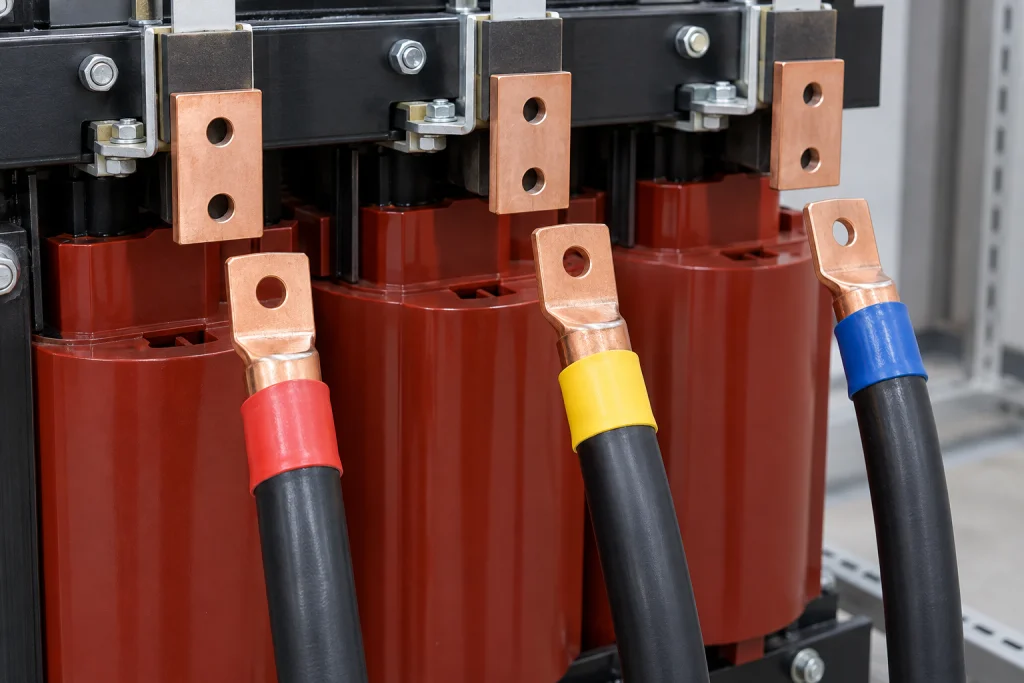
Build one schedule linking each proposed cable to its connector and terminal. Request cable type, conductor material, size and parallel quantity, together with the connector envelope and hole geometry. Ask the transformer supplier to confirm the accommodated connections against the actual terminal provision; do not assume a hole accepts any proposed lug arrangement.
Eaton's low-voltage manual selects connectors by cable type and size and directs tightening to the connector manufacturer's recommendations. The Raychem RPG VPI manual limits cable-box terminations to the number of provided busbar holes and prohibits additional site holes in those busbars. That restriction belongs to its VPI arrangement, separately from enclosure gland-plate machining.
The joint specification also depends on the actual metal pairing and contact treatment:
| Manufacturer example | Condition and instruction |
|---|---|
| Rex Power Magnetics field connections | Its field-connection contact surfaces are tin-plated; the connecting lug or bus should be tin- or silver-plated, with the recommended torque followed. |
| BTicino joint instruction | When untreated copper busbars connect to its LV aluminium terminals, CU-PAL intermediate plates are necessary to prevent corrosion from direct copper-to-aluminium contact. |
| Raychem RPG VPI connections | Its instruction says bimetallic lugs should be used when aluminium cables connect to copper busbars. |
These arrangements are not interchangeable solutions for every mixed-metal joint. Request the selected assembly's terminal and conductor metals, contact treatment, applicable transition component, connector arrangement and tightening instructions. Confirm the actual termination capacity rather than adopting a universal lug-stacking rule.
Obtain supplier agreement on geometry, termination quantity and the complete joint assembly before ordering connection hardware. Keep missing dimensions or assembly instructions open; no generic torque table resolves them. 234910
What confirms busway fit and conductor support?
When busway is selected, use a shared mating drawing reviewed by both suppliers to coordinate electrical assignments, physical dimensions, links and supply boundaries. Separately agree external conductor supports and the applicable flexible electrical connection arrangement before accepting the layout for ordering. 3456711
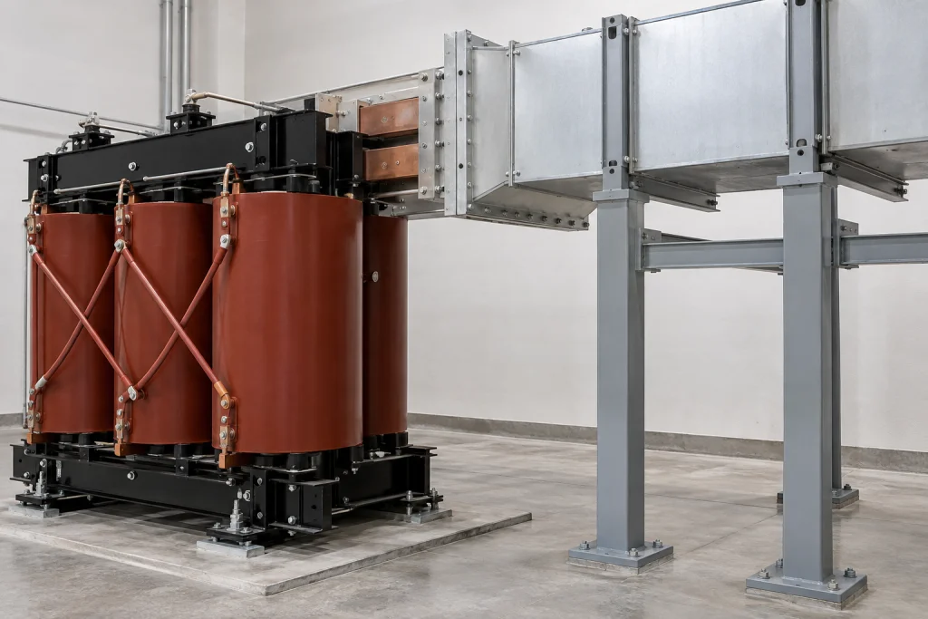
A connection diagram alone is not a dimensional mating approval. For your selected transformer and busway, request one drawing showing corresponding terminal assignments, orientation, physical mating dimensions and connection links, including applicable phase, neutral and earth arrangements. Ask both suppliers to review their interfaces and record who supplies each connection component.
Maddox's low-voltage busway guidance recommends flexible connectors and says connections should conform to the nameplate drawing or connection diagrams. That recommendation informs the review; compatibility still needs confirmation for the selected transformer and busway.
Support is a separate decision. Schneider's cast resin support instruction, for its unenclosed arrangement, requires adequate cable and busbar support to prevent mechanical stress on transformer terminals, busbars or bushings. Request agreement on the external support designer, supplier and approver, then obtain confirmation of support locations and permissible terminal loads.
For its VPI busbar joints, Raychem RPG calls for alignment before bolting to prevent excessive insulator strain. BTicino requires flexible electrical connections in its specified cast resin busbar arrangement to mechanically isolate the transformer from the busbars. Preserve that requirement's scope rather than treating every flexible-link arrangement as equivalent. Eaton's flexible-conduit instruction concerns a separate component; conduit does not establish an electrical bus-link arrangement.
For the order review, check both suppliers' responses against the mating geometry, connection scope and agreed support and flexible-link arrangements for the selected configuration. 3456711
Which routing spaces require separate checks?
Check cable bending space, electrical separation and ventilation as distinct constraints on the complete conductor route, with connectors installed. Obtain the selected cable's bending requirement and applicable equipment clearances, then confirm that the entry arrangement preserves ventilation openings and the room airflow path. 1212
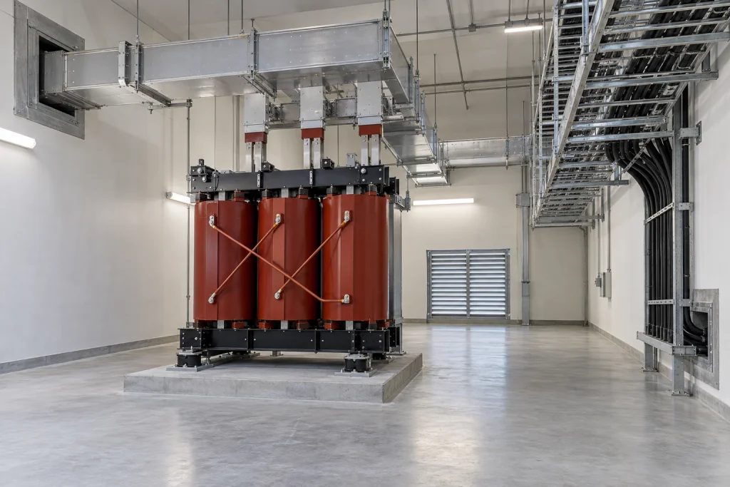
Annotate the proposed route on the coordinated equipment and room layout. Distinguish three spaces rather than applying one general clearance:
- Cable bending space: request the selected cable's bending requirement and show how the cable and connector fit between the entry and terminal.
- Electrical separation: obtain the applicable equipment clearances and review the installed conductor and connector geometry against them.
- Ventilation path: show the enclosure ventilation openings and room inlet-to-outlet path, then check the proposed route for obstruction.
The ABB low-voltage entry guidance links the outline drawing and required bending radius, recommending side entry for that equipment to leave ventilation areas unobstructed. Siemens' cast resin guidance separately calls for sufficient cable-connection space and electrical distance. Neither establishes a universal dimension for another configuration.
Hitachi Energy's dry-type guidance says supply cables should contact no live part except their intended terminal and calls for free air circulation. Its room-ventilation instruction says inlet and outlet openings should remain permanently open for continuous ventilation.
Review the complete route with connectors in place against the applicable bending, electrical and airflow constraints before ordering. Obtain dimensions from the selected equipment suppliers and project design; this connection-route review does not replace room ventilation design. 1212
What closes interfaces before manufacturing release?
Record each connection decision against the selected configuration, responsible party, drawing revision and review evidence. Identify the authorized manufacturing revision and release authority under the project's agreed procedure, close fit-critical open items, and trace later changes into affected drawings and procurement inputs. 7
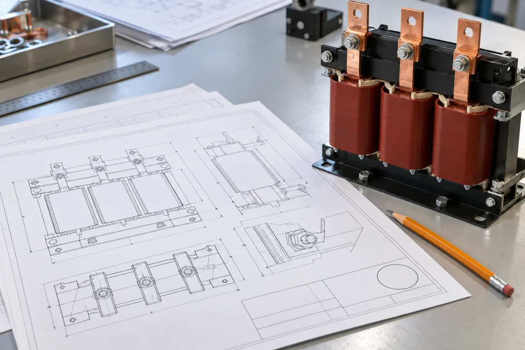
I recommend using an interface register to link each decision to the controlled drawing revision used for manufacture before releasing affected details. This is a procurement recommendation under your project's agreed approval procedure, not a universal release requirement.
Use separate rows for entry and terminal geometry, cable/lug fit, joint assembly, busway mating where selected, supports and flexible links, routing spaces, and gland-plate work. A practical register contains:
| Field | Record to request |
|---|---|
| Interface and required input | The decision and information needed to resolve it |
| Responsible party | Who supplies the input and who reviews it |
| Model/configuration | The equipment arrangement the decision covers |
| Document number and revision | The drawing or procurement input carrying the decision |
| Review evidence and closure status | The recorded response and whether the item remains open |
| Change reference | The reference linking a later change to affected documents |
The EPC interface-closure guidance connects inputs, owners, review status and affected documents, with traceable changes after closure. Apply that record structure only to the connection decisions covered here.
Before the order and manufacturing release, identify the project party authorized to release the affected details and the exact manufacturing revision. Close fit-critical open items under the agreed procedure; trace later changes into the relevant interface drawings and procurement inputs. 7
Which Inputs Require Final Confirmation?
Start the supplier discussion with the selected cast resin configuration, proposed cable/connector schedule or busway interface, and coordinated entry drawings. Resolve terminal fit, joint assembly, supports and routing spaces, then record the agreed revision and release authority.
Leave unresolved supplier inputs open in the register, and close fit-critical items before authorizing affected manufacturing details. 134567910
References
- ABB. ↩ ↩ ↩ ↩ ↩ ↩
- Siemens. ↩ ↩ ↩ ↩ ↩ ↩ ↩
- Eaton. ↩ ↩ ↩ ↩ ↩ ↩
- Raychem RPG. ↩ ↩ ↩ ↩ ↩ ↩
- Maddox Transformer. ↩ ↩ ↩ ↩
- Schneider Electric. ↩ ↩ ↩ ↩
- Closing Transformer Technical Interfaces in EPC Projects. ↩ ↩ ↩ ↩ ↩ ↩ ↩ ↩
- Siemens Energy. ↩ ↩
- Rex Power Magnetics. ↩ ↩ ↩
- BTicino. ↩ ↩ ↩
- BTicino. ↩ ↩
- Hitachi Energy. ↩ ↩