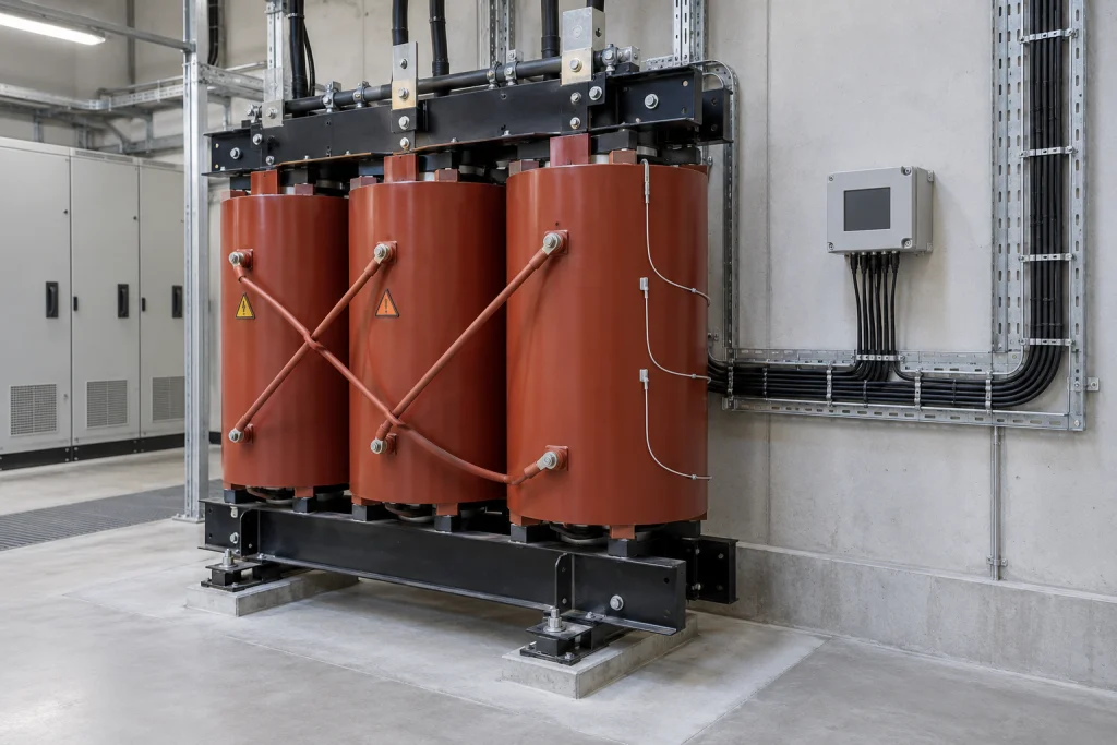
A cast-resin transformer RFQ that says only “temperature monitoring” leaves the supplier's proposed sensor arrangement, warning and trip functions, and control device open to clarification. You need those details to assess the proposed monitoring arrangement for an indoor distribution project.
I start with the sensor arrangement and the intended warning and trip destinations because a probe designation alone does not describe the protection interface. SGB-SMIT's Planning Guide and Legrand's LE06499AF manual provide bounded manufacturer examples for framing the questions.
Use this fast input checklist when preparing the RFQ:
- Ask the supplier to identify the proposed winding sensors and their location.
- Identify any requested core monitoring and ask whether the supplier offers it.
- Request the actual sensor count and connections, with separate intended warning and trip destinations.
- Ask for the matching temperature-control device, probe connection diagram, programming instructions, number and functions of electrical contacts, terminal numbering, and supplier-confirmed settings.
- Ask the supplier and EPC room designer to confirm enclosure rating, ventilation, noise level, partial discharge and temperature monitoring requirements together with the installation room.
These are requests for a defined proposal. The manufacturer examples below do not establish another supplier's options, device compatibility or scope of supply. 12
Which temperature sensor arrangement should EPCs specify?
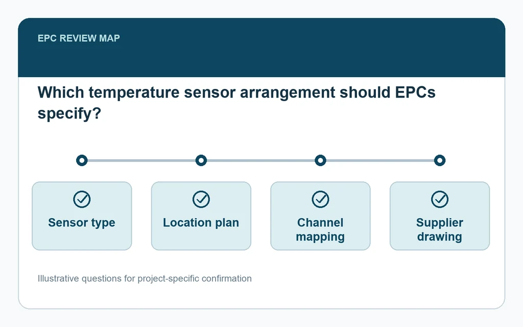
Specify the proposed winding-sensor arrangement and identify any requested core monitoring separately. SGB-SMIT describes PTC sensors in low-voltage windings as its general arrangement, with PT100 and core-monitoring options on request. Before ordering, ask the supplier to confirm the arrangement and matching control device. 1
The SGB-SMIT Planning Guide describes PTC sensors as resistors whose resistance changes rapidly when the response temperature is reached. It places those sensors in the low-voltage windings. That gives the RFQ a concrete starting point: ask what winding sensors the supplier proposes and where they are located, rather than leaving the arrangement under a general accessory description.
The guide separately identifies PT100 and core monitoring using PT100 or PTC as options on customer request. Keep those requests distinct. Asking for PT100 winding sensors does not, by itself, define a core-monitoring arrangement. Likewise, a request for core monitoring should ask which sensor arrangement the supplier proposes for that function.
These are SGB-SMIT's described arrangements and options. They do not establish universal availability across cast-resin transformer manufacturers.
A practical RFQ request is: “Please identify the proposed winding-sensor type and location, confirm whether the requested core monitoring is offered and describe its sensor arrangement, and identify the matching temperature-control device.”
Before ordering, check that the supplier's response distinguishes the winding arrangement from any requested core monitoring. Keep unanswered options open for clarification. 1
How should warning and trip functions differ?
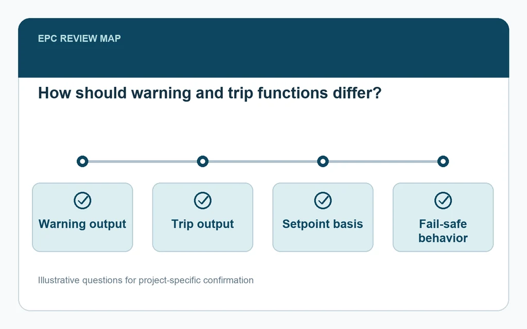
Describe warning and trip as separate functions and ask where each is intended to act. SGB-SMIT describes warning as prompting off-load measures and tripping as requiring transformer shutdown. Before ordering, confirm the supplier's actual sensor count, connections and intended destinations for both functions. 1
SGB-SMIT distinguishes the functions by their purpose. Its warning system signals an overshoot of the temperature associated with normal service-life consumption, described as continuous rated load at a cooling-medium temperature of 20°C. The warning is intended to alert the plant operator and prompt off-load measures.
The guide describes the second system as adapted to the limit temperature of the declared temperature class. In that case, the transformer must be switched off. The warning and trip descriptions therefore call for different responses; the RFQ should ask the supplier to identify the intended destination of each function.
I keep the intended response beside each function when reviewing a proposal, so “alarm and trip” does not remain an unexplained pair of labels. Ask the supplier where the warning is intended to be received and where the trip is intended to initiate shutdown. Those questions do not establish that particular interfaces are included in the offered equipment.
The guide also describes three resistors connected in series to a terminal strip, explicitly qualifying the example as one sensor per phase. It is an illustrated arrangement, not a universal sensor count or connection requirement.
Before ordering, ask the supplier to state the actual sensor count, connections and intended warning and trip destinations for the proposed arrangement. Resolve those details without copying the example's configuration into the RFQ as a requirement. 1
Which control device details require supplier confirmation?
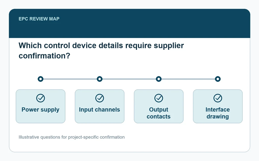
Ask for the selected control device, probe connections, programming instructions, contact count and functions, terminal numbering, and confirmed settings. Legrand directs connection, programming, contact and terminal details to device manuals; its setting table is indicative. Confirm compatibility and supply inclusion before ordering. 2
The Legrand LE06499AF manual identifies Pt100 probes according to IEC 60751 or PTC probes according to DIN 44081 as alternatives. That statement describes probe alternatives within the manual's scope. It does not establish that any particular control device accepts both types or that the device is included in another supplier's offer.
For probe connections to the control unit and programming, Legrand refers readers to the manufacturer's manual. It also states that electrical connection diagrams, the number and function of electrical contacts, and terminal numbering are detailed in the temperature-control-device manuals. The selected device's documentation is therefore the reference for checking those details.
Ask the supplier to name the proposed device and provide the relevant documentation. Review the probe connection diagram against the proposed sensor arrangement, then ask the supplier to identify the contacts and terminals intended for the warning and trip destinations. Treat compatibility and supply inclusion as questions requiring an explicit response.
Legrand describes the values in its setting table as indicative and not prescriptive. Do not turn that table into RFQ settings. Request supplier-confirmed settings for the proposed arrangement and the programming instructions for the selected device, without assuming that an illustrative value is the correct value for the proposal.
Before ordering, check that the supplier's response identifies the device, resolves the sensor connection questions, and states the contact functions, terminal numbering and confirmed settings. Any unanswered item remains open for clarification. 2
Which Inputs Require Final Confirmation?
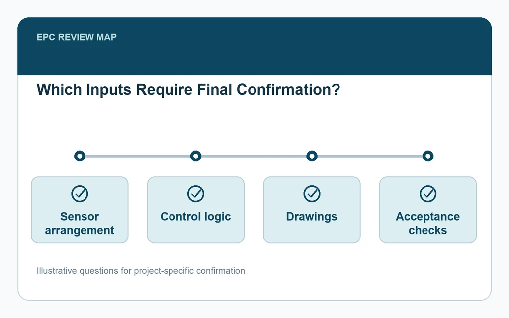
The supplier’s proposed winding and requested core-monitoring arrangement, intended warning and trip actions, and control device need final confirmation before ordering. The documentation must define the connections and settings, while unanswered compatibility, interface or supply questions remain open until clarified.
Before ordering, resolve three linked questions: what winding and requested core-monitoring arrangement the supplier proposes, how warning and trip are intended to act, and which control device and documentation define the connections and settings. Keep the SGB-SMIT arrangements as attributed examples and Legrand's setting table as indicative guidance. Use the temperature-monitoring requirements in your RFQ to request a specific supplier response, and leave unanswered compatibility, interface or supply questions open until clarified. 12