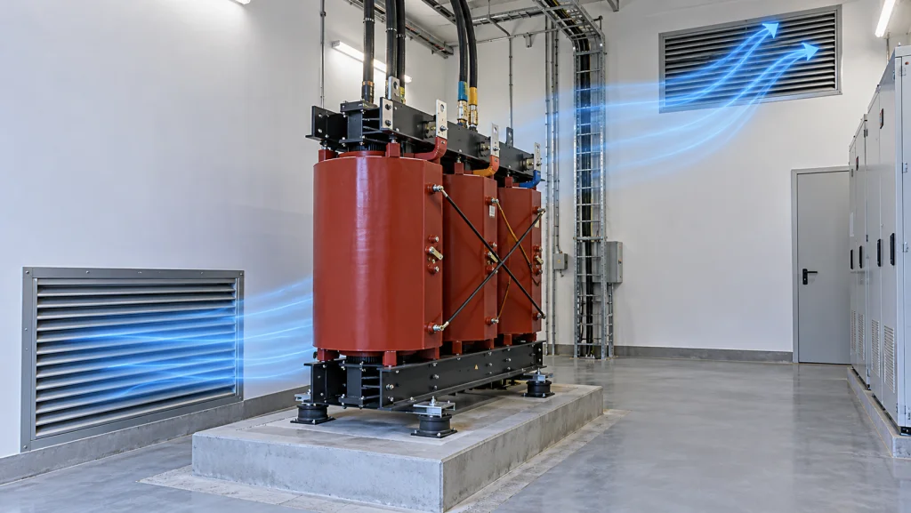
A room-ventilation RFQ needs more than an opening area: an EPC electrical engineer needs to understand the loss input, the calculation condition and the airflow arrangement behind that area. I start with those three points because a calculated opening is useful only when its inputs and scope are clear.
For discussion of Legrand LE06499AF, prepare this short input checklist:
- No-load and load losses in kW indicated on the transformer test report, whose sum Legrand calls TL.
- H, the height between the two openings in metres.
- The formula’s stated annual-average temperature condition of 20°C.
- A low fresh-air inlet and a high outlet on the opposite wall.
- Whether the transformer has a protective enclosure, because Legrand attaches its surrounding-wall spacing requirement to that condition.
Alongside room ventilation, ask the selected supplier these open questions for joint confirmation with your EPC electrical engineer:
- Which protective enclosure rating suits the installation room?
- Which noise level should be specified for the installation room?
- Which partial discharge requirements should be confirmed for the transformer in that room?
- Which temperature monitoring arrangements should be coordinated with the room?
The following manufacturer example helps your project procurement team frame questions for the selected cast-resin transformer supplier. It does not establish final room opening dimensions. 1
Which losses enter Legrand’s ventilation calculation?
Legrand uses TL as the sum of no-load and load losses in kW indicated on the transformer test report. Those losses become heat that the room must dissipate, so the selected transformer’s loss values are the starting point for discussing this calculation. 1
Page 18 of Legrand LE06499AF connects the losses shown on the test report to heat that must be dissipated from the installation room. Legrand applies that statement to transformers with or without protective enclosures, explaining that heat dissipation maintains normal-use conditions and prevents over-temperature limits from being exceeded.
The loss input is therefore a defined quantity, not a value to infer from the transformer’s rated power. In Legrand’s notation:
TL = no-load losses + load losses, expressed in kW and indicated on the test report.
I keep the two loss components visible in the RFQ discussion so the supplier can confirm what enters the sum. Before ordering, ask: “For the selected transformer, what no-load and load loss values should we use when discussing Legrand’s calculation, and are those values indicated on its test report?”
That question seeks confirmation of the calculation inputs. It does not establish a document-delivery obligation or guarantee loss values for equipment offered by ZoeTransformer. 1
How does Legrand calculate net opening areas?
Legrand calculates net inlet area as S = 0.185 × TL / √H and net outlet area as S′ = 1.15 × S, under an annual-average temperature condition of 20°C. Keep the definitions and condition beside the arithmetic before discussing its applicability with the selected supplier. 1
Page 18 gives these equations for determining minimum opening areas under its stated condition:
S = 0.185 × TL / √H
S′ = 1.15 × S
The definitions belong alongside the equations:
| Symbol | Legrand’s definition | Unit |
|---|---|---|
| S | Net entry surface | m² |
| S′ | Net exit surface | m² |
| TL | Sum of no-load and load losses indicated on the test report | kW |
| H | Height between the two openings | metres |
Retain H as the height between the openings when discussing the example; do not add measurement endpoints to that definition. Likewise, retain “net” when recording the entry and exit areas.
For a clearly hypothetical calculation, assume TL = 10 kW and H = 2 m under the stated annual-average temperature condition of 20°C:
S = 0.185 × 10 / √2 ≈ 1.308 m²
S′ = 1.15 × S ≈ 1.504 m²
The 10 kW loss input and 2 m opening height are assumptions for this arithmetic, not values for a supplied transformer or an actual room. The result illustrates how Legrand’s definitions enter its equations.
Before ordering, ask the selected supplier to confirm the TL and H inputs and discuss the stated temperature condition for this example. Keep that discussion separate from acceptance of final project opening dimensions. This Legrand manufacturer example is not universal sizing guidance or a guaranteed project design, and it does not establish final project opening dimensions. 1
Hypothetical opening-area calculation: Assume TL = 10 kW and H = 2 m under Legrand’s stated annual-average temperature condition of 20°C. Its equations give S ≈ 1.308 m² and S′ ≈ 1.504 m². These assumed inputs and calculated areas do not establish final project opening dimensions. 1
What airflow arrangement does Legrand specify?
Legrand places the fresh-air inlet low and the heated-air outlet high on the opposite wall for chimney-effect ventilation. Separately, it requires at least 0.3 m from surrounding walls for transformers with protective enclosures to allow air circulation. Confirm the selected supplier’s arrangement before ordering. 1
On page 18, inlet S sits in the lower part of the room to admit fresh air. Outlet S′ sits high on the opposite wall to extract heated air rising through the chimney effect. The arrangement explains the intended air path behind the opening-area calculation: fresh air enters low, while heated air leaves high on the opposite side.
For your RFQ discussion, identify which proposed opening is the inlet and which is the outlet. An area calculation alone does not describe their positions; Legrand’s example includes both the net areas and the low-to-high, opposite-wall arrangement.
Page 19 addresses a separate condition. For transformers provided with protective enclosures, Legrand specifies placement no closer than 0.3 m from surrounding walls to allow air circulation. Keep the protective-enclosure condition attached to that spacing statement. It is a Legrand-specific requirement, rather than a universal clearance for every cast-resin transformer.
These statements describe Legrand’s arrangement; they do not assess an actual project layout. Before ordering, ask: “What inlet, outlet and enclosure wall-spacing arrangement does the selected supplier specify for its transformer?” Resolve that question alongside the loss inputs and calculation condition, so the ventilation discussion covers the air path as well as the calculated areas. 1
Which Inputs Require Final Confirmation?
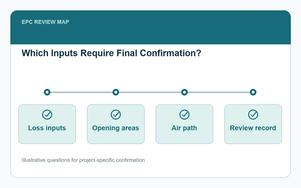
Confirm no-load and load losses, H between openings, Legrand’s stated annual-average temperature condition of 20°C, and the supplier’s inlet, outlet and protective-enclosure wall-spacing arrangement. Alongside room ventilation, resolve open supplier questions about protective enclosure rating, noise level, partial discharge and temperature monitoring with your EPC electrical engineer.
Before ordering the selected cast-resin transformer, I use the hypothetical calculation to clarify these questions, while keeping final project opening dimensions separate from this manufacturer example. 1