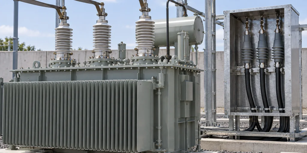
An oil-immersed transformer offer can state voltage and current yet leave the cable connection unresolved. As an EPC electrical engineer, you need to establish what must mate, what must fit and who confirms each part.
I start with the connection arrangement and cable data because neither a transformer rating nor a connector-family label confirms the proposed assembly.
For a fast RFQ input check, gather:
- The single-line diagram, system voltage and frequency, insulation duty, fault level, loading requirements and any required overload.
- The intended MV and LV connection methods, connected equipment, cable-entry direction and enclosure arrangement.
- Cable insulation type, conductor material and cross-section, insulation diameter and circuits per phase.
- Cable routing and bending requirements, terminal positions and phase identification.
- Proposed component supply boundaries and the documents requested for interface review.
Use these inputs to request confirmation of the proposed assembly. Keep unresolved values visible for project engineering review rather than treating a connection label as a completed interface specification. 123456
What connection arrangement and responsibilities should RFQs define?
RFQs should identify the MV and LV connection methods, connected equipment, cable-entry direction and enclosure arrangement, then propose who supplies and reviews each applicable component. Keep housing material, connection method and enclosure arrangement as separate decisions. 1
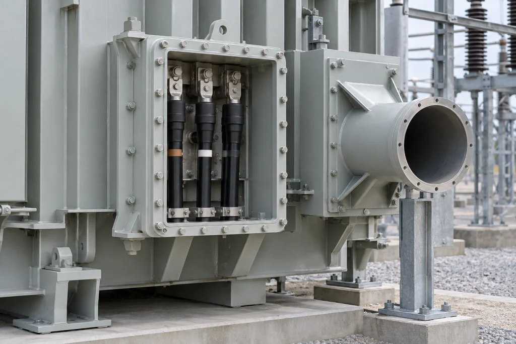
A separable-connector connection, a busbar connection and a cable compartment describe different aspects of the arrangement. Specifying porcelain or polymer housing does not settle how the cable mates or which enclosure surrounds it.
Show the intended MV and LV paths, adjacent equipment and top, side or bottom cable approach on a connection sketch. Identify the proposed connection method and enclosure separately on each side.
I recommend a proposed interface register linked to that sketch, with one line for each applicable bushing, mating connector or terminal connection, cable-box component and grounding interface. Record its proposed supplier, information owner and reviewer. The register is a way to agree responsibilities, rather than an allocation imposed by a standard.
Ask the transformer supplier to identify proposed components and exclusions. Before ordering, agree the supply boundary and who reviews the complete interface, including parts supplied separately. 1
Which electrical and thermal duties govern terminal selection?
Select terminal ratings against the project's voltage, frequency, current, insulation and fault duties, with neutral duty identified separately where applicable. Any required overload needs an application-specific thermal assessment; the transformer rating alone does not establish the bushing and connection assembly's capability. 1567
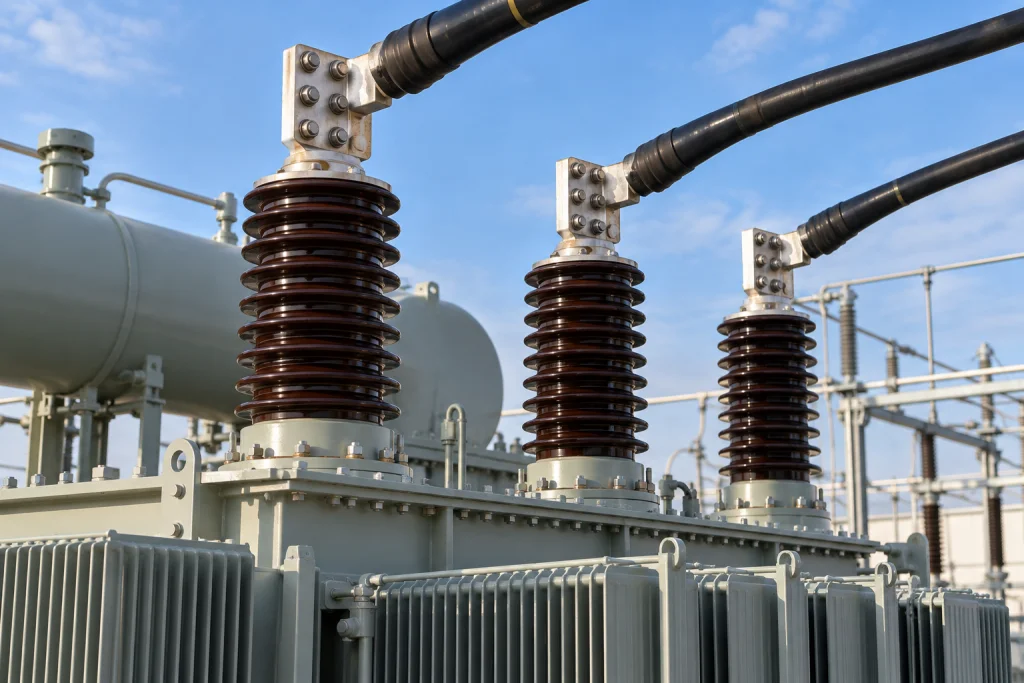
Build a terminal-duty schedule from the single-line diagram and loading requirements. Record system voltage and frequency, highest system voltage and required insulation levels, continuous-current duty, fault level and any required overload. Ask the supplier to confirm the proposed bushing and connection assembly's ratings against those inputs using current manufacturer data for the offered configuration.
Treat an applicable neutral connection as a separate schedule line. For a project adopting IOGP/JIP33 S-720 v2020-12, check the LV-neutral connection against that edition's stated minimum of 50% or greater of phase current for polyphase liquid-immersed distribution transformers. That edition-specific minimum does not confirm a currently offered component's rating or establish the current duty needed by a particular project's neutral connection.
Where overload is required, request an assessment for the application. Ask the supplier to address transformer top-oil temperature before and after overload, ambient temperature, terminal or metallic hot-spot conditions and allowable bushing loss of life. A nominal current rating does not answer those thermal questions.
Have the electrical engineer identify unresolved duty values and ask the supplier to state the assumptions used for its proposed assembly. Before ordering, resolve those values and check that the confirmed ratings address each applicable terminal and the requested loading conditions. 1567
What confirms bushing, connector and cable compatibility?
Compatibility requires the identified bushing interface, exact connector variant and actual cable construction and dimensions to be checked together. Shared voltage and current labels do not establish a matched assembly, and a product-family range does not establish every variant's applicability. 248
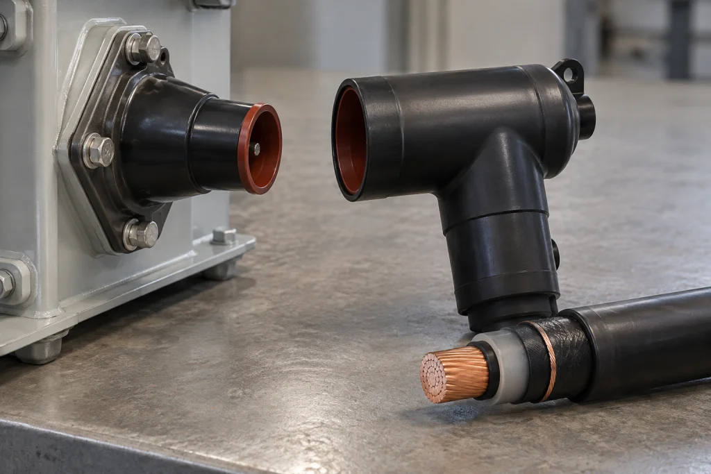
Request the bushing interface identification and connector part number alongside the cable insulation type, conductor material and cross-section, and insulation diameter. Those details allow the proposed mating interface and cable applicability to be reviewed together.
For example, TE Connectivity's RSES/RSSS product page described screened separable connectors for Interface Type A bushings up to 24 kV and 250 A. It listed several compatible insulation-diameter ranges across the family. Do not apply the family's overall range to a selected variant without checking that variant's data.
The Nexans Interface D document separately provided dimensional interface information. These Type A and Interface D examples show the information to request; they do not confirm current product specifications, establish interchangeability between the families or identify a ZoeTransformer offering.
Ask for the referenced product data, confirmation from the manufacturer that those data remain current, and a matched interface drawing or equivalent manufacturer confirmation naming the proposed components. Before ordering, check the exact connector variant against both the bushing interface and the actual cable data. Leave the assembly match open wherever those confirmations remain pending. 248
Which drawings confirm terminal layout and cable routing?
Terminal and outline drawings should be reviewed together with the cable schedule and routing sketch. Confirm terminal positions, phase identification, entry direction, bending space, access and supports using a common viewing direction, with dimensions and permissible connection loads confirmed by the relevant manufacturers. 1236
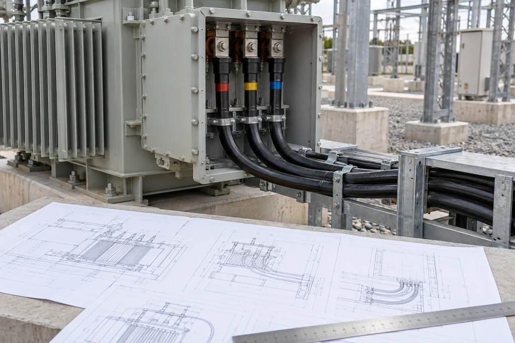
An electrically compatible connector still needs a workable cable route and connection space. Bring the cable schedule, routing sketch and proposed terminal and outline drawings into the same review.
Include cable insulation type, conductor material and cross-section, insulation diameter and circuits per phase. Supply the applicable cable bending requirements, then show the intended entry direction, termination envelope, access and proposed supports. Ask the supplier to show the available connection space against that route.
When I review a terminal drawing, I check the viewing direction and cable approach together before treating the layout as settled. Identify terminal positions and phase labels in the same view used for the adjacent equipment. A phase-label sequence read from one side should not be transferred to another view without checking the orientation; an application example does not establish a universal mirroring rule.
Use a common viewing arrow and identify the drawing revision submitted for review. Agree a named reviewer for the coordinated arrangement so that comments on cable routing and terminal positions can be resolved together.
Request manufacturer-confirmed dimensions and permissible connection loads. Have the proposed support arrangement reviewed against cable forces and the applicable terminal limits; qualitative support guidance supplies no project force limit. If a sketch is conceptual, label it as a procurement aid rather than an approved arrangement.
Before ordering, check the proposed drawing against the cable schedule, adjacent equipment and confirmed space and load limits, then resolve remaining layout comments. 1236
Which cable-box details depend on the selected configuration?
Cable-box details depend on the selected construction and the specification adopted by the project. Separate provisions for air-insulated connection space from liquid-filled-box fittings, preserve every 'where specified' condition, and request confirmation of the construction and fittings actually offered. 179
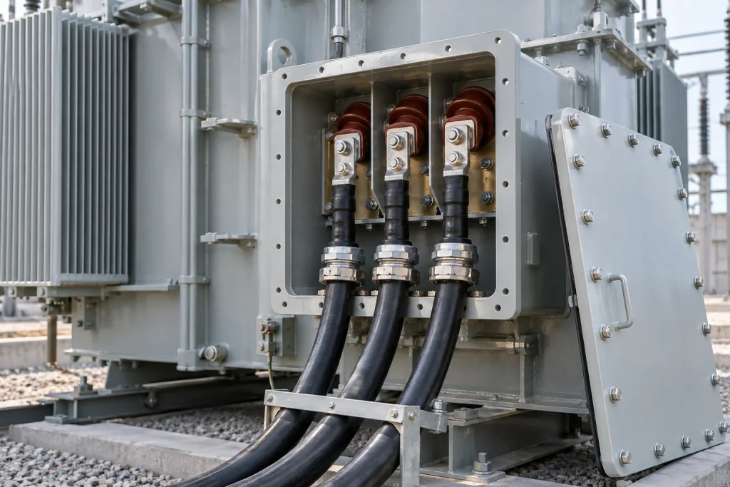
Ask for a cable-box schedule covering construction, connection space, cover access, sealing, grounding and applicable fittings. Record the project selections separately from the supplier's proposed construction.
If the project adopts IOGP/JIP33 S-720 v2020-12, apply its provisions to the relevant configuration:
| Configuration or condition | Provision to address |
|---|---|
| Cable connecting boxes under the S-720 v2020-12 provisions | Steel construction, dimensions for air-insulated connections and captive cover bolts or screws |
| Outdoor cable connecting boxes | Metal canopies only “where specified” |
| Liquid-filled cable boxes | Liquid sampling/drain valve and vent plug |
| Liquid-filled cable boxes, “where specified” | Pressure-relief device with trip contacts |
The air-insulated connection-space provision and the liquid-filled-box fittings describe separate configuration provisions. Do not combine them into a default arrangement.
The companion S-720D v2020-12 data sheet has a Yes/No selection for a pressure-relief device on a liquid-filled cable box. The field calls for a project decision; it does not select a device or establish an offered option.
Before ordering, confirm which provisions apply and ask the supplier to identify the offered construction, access, sealing, grounding and selected fittings on the proposed schedule and drawing. 179
Which standards and evidence apply to the offered interface?
Define the applicable components, adopted standard editions and assessment boundary, then request documents for the exact offered configuration. Dimensional references, proposed tests, report formats and completed applicable reports answer different questions; none should be treated as a substitute for the others. 14810
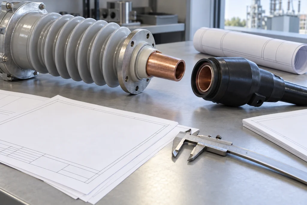
Keep transformer, bushing and connector requirements separate in the interface schedule. For each applicable item, record the project-adopted edition, proposed component, document reference and agreed reviewer.
IEC 60137:2017, Edition 7.0, specifies characteristics and tests for insulated bushings for three-phase AC systems above 1 kV, including use in transformers. It applies to bushings made and sold separately. A bushing that forms part of apparatus and cannot be tested according to that standard should be tested with the apparatus. Ask the supplier to identify which assessment boundary applies to the proposed bushing.
Nexans reports EN 50180 and EN 50181 as dimensional references in its Interface D material. Keep those references separate from qualification of the proposed assembly. Ask the supplier to identify the standard editions used for the proposed components' assessment, separately from the editions named in the RFQ.
My final check is whether each technical claim can be traced to the proposed component and configuration. Request:
- Technical data and outline and terminal drawings.
- Wiring details where applicable and installation instructions.
- The routine-test report format and applicable type-test evidence.
- Project-specific compliance documents for the interface.
For the proposed document register, identify revision, model and configuration, plus any explanation needed to apply an existing report to the offered assembly. Agree which documents are intended for quotation review and which are proposed later deliverables.
Distinguish a report format from a proposed test and from a completed report. Describe a test as available on request only after the supplier confirms it can be arranged; a completed-test claim needs an identified report and its model and configuration. A standards reference does not establish certification or technical acceptance. Before ordering, confirm document commitments and test availability, resolve applicability questions with the agreed reviewers, and keep unreviewed lines open. 14810
Which Inputs Require Final Confirmation?
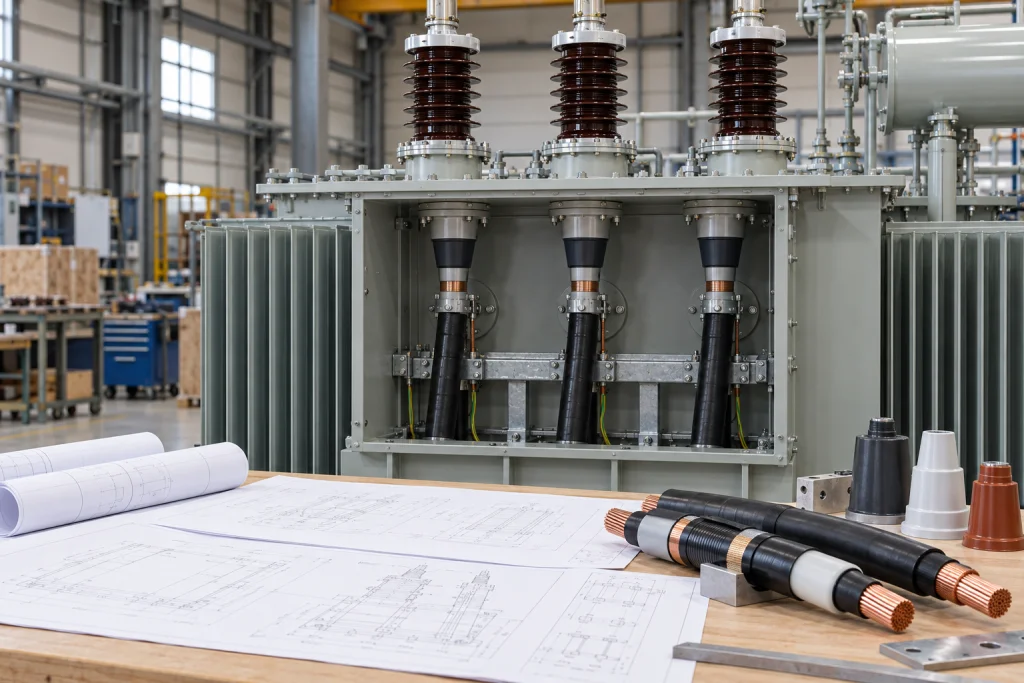
Send the single-line diagram, cable schedule and connection sketch with the RFQ, and ask ZoeTransformer to confirm the proposed interface, component supply and exclusions. Before ordering, have the agreed reviewers resolve open duty, compatibility, layout, cable-box and evidence questions for the offered configuration. 12347810
References
- Transformer Bushing and Cable Box Design. ↩ ↩ ↩ ↩ ↩ ↩ ↩ ↩ ↩ ↩ ↩ ↩
- Interface F Bushings & High Voltage Power Cable .... ↩ ↩ ↩ ↩ ↩ ↩
- Guide to Substation Bushings. ↩ ↩ ↩ ↩
- TE Connectivity. ↩ ↩ ↩ ↩ ↩ ↩
- IEEE Transformers Subcommittee Bushing Overload Task Force. ↩ ↩ ↩
- Transformer Bushing Selection Guide. ↩ ↩ ↩ ↩ ↩
- International Association of Oil & Gas Producers, JIP33. ↩ ↩ ↩ ↩ ↩
- Nexans. ↩ ↩ ↩ ↩ ↩
- International Association of Oil & Gas Producers, JIP33. ↩ ↩
- International Electrotechnical Commission. ↩ ↩ ↩